|
|
The Clem engine
There is always new and exciting discoveries happening.
|
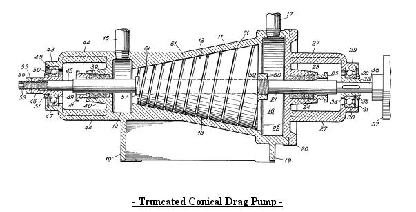 Clem Cone pump.
Housing 11, Conical interior wall 12, Conical rotor 13, Inlet chamber 14, Inlet pipe 15, Outlet chamber 16, Outlet pipe 17, Support feet 19, Detachable end cap 20, Rotor shaft 21, End cap wall 22, Boss 23, Packing 24, Adjustable gland nut 25, Bracket arms 27, Bearing boss 29, Bearing 30, Snap ring 31, Inner race 32, Sleeve 33, Shoulder 34, Retainer nut 35, Reduced diameter outer end 36, Coupling 37, Packing 39, Retainer 40, Gland nut 41, Bearing boss 43, Integrally formed bracket 44, Shaft reduced diameter 45, Bearing sleeve 46, Bearing 47, Snap ring 48, Inner flanged 49, Inner race 50, Nut 51,Shaft reduced diameter 53, Lock nut 55, Flat faces 56, Snap ring 57, Washer 59, Nut 60, Helical channel 61, Channel base 63, Channel sidewalls 64
Clem Cone pump.
Housing 11, Conical interior wall 12, Conical rotor 13, Inlet chamber 14, Inlet pipe 15, Outlet chamber 16, Outlet pipe 17, Support feet 19, Detachable end cap 20, Rotor shaft 21, End cap wall 22, Boss 23, Packing 24, Adjustable gland nut 25, Bracket arms 27, Bearing boss 29, Bearing 30, Snap ring 31, Inner race 32, Sleeve 33, Shoulder 34, Retainer nut 35, Reduced diameter outer end 36, Coupling 37, Packing 39, Retainer 40, Gland nut 41, Bearing boss 43, Integrally formed bracket 44, Shaft reduced diameter 45, Bearing sleeve 46, Bearing 47, Snap ring 48, Inner flanged 49, Inner race 50, Nut 51,Shaft reduced diameter 53, Lock nut 55, Flat faces 56, Snap ring 57, Washer 59, Nut 60, Helical channel 61, Channel base 63, Channel sidewalls 64
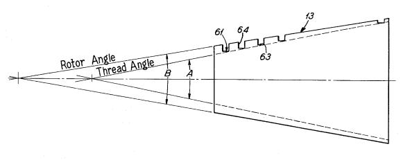
This is a high-pressure, low volume drag pump that can be used in place of conventional positive displacement pumps (criteria 2). It has a conical rotor that has a close fit clearance with the stationary housing wall. Delivered pressure is limited by back flow across the radial clearance and is inversely proportional to the square of the clearance. As a result, even a small increase in radial clearance would rapidly reduce pressure. The rotor is cone shaped so that the clearance can be controlled by axial adjustment of the rotor relative to the housing wall.
The conical rotor has two helical channels (criteria 3), in the form of square threads, spaced 180� apart for balance. The channel depth decreases as the rotor diameter increases. Fluid enters the channels at the small end of the rotor. The fluid is induced to rotate with the channel by boundary layer drag. The boundary layer is the thin layer of fluid adhering to the channel surface. Molecular cohesion tends to drag the adjacent fluid with the boundary layer. The fluid is also in contact with the housing wall. The boundary layer drag against this stationary wall slows the rotation of the fluid in the channels. Because the fluid rotates slower than the rotor, it’s forced through the channels towards the large end of the rotor. In addition the fluid is forced towards the large end by centrifugal force.
|
|
The Clem engine worked on vegetable oil and developped 300 HP.
|
|
The Richard Clem Motor and the Conical Pump
The above drawing illustrates the proportional decrease in channel depth as the rotor diameter increases. Why was this done? Note that as the diameter doubles so does the circumference. This means the fluid has to travel twice as far in the same time to maintain a constant slip velocity. By reducing the channel depth in half (cross-section area = depth x width) the fluid velocity is doubled thereby keeping the slip constant.
The spiral channels could be thought of as very long convergent nozzles. The increase in fluid velocity is in the opposite direction of the rotor spin. We should expect a reaction force from the acceleration of the fluid. This thrust would be directed tangent to the circumference and would increase the spin torque on the rotor. Even without the peripheral nozzles, that Clem later added, the pump rotor experiences a thrust force in a direction that would self-propel it (criteria 4).
Because fluid drag is the primary pumping force, it is well suited for viscous fluids like asphalt (criteria 5). The long channels also represent a large sliding surface area with frictional losses that would transfer heat to the pumped fluid (criteria 6).
All six of the patent search criteria have now been met. Of course this doesn’t prove that it is the asphalt pump Richard Clem worked with.
A peculiar condition indicated by the patent is that as the velocity increases in the channels the pressure also increases. Bernoulli’s Law requires the pressure to drop proportionally as the velocity increases. Assuming an ideal fluid without losses, when the channel depth is reduced in half, the cross section area is also half and this doubles the fluid velocity and the fluid pressure should drop in half. So what is going on here? There is a centrifugal component that would add to the fluid pressure.
My guess is it’s too small to overcome the predicted pressure drop. Here is what I think may be going on. As the diameter and velocity increases the drag force propelling the fluid through the channel is proportionally greater. Energy is being added all along the length of the channel. Whatever the reason, if this high-velocity, high-pressure fluid is feed into tangent peripheral nozzles at the rotor large end, the energy will be converted to shaft horsepower.
The Clem motor is producing 350 shaft-horsepower and a large heat energy component. Where is this huge amount of energy coming from? Resent quantum mechanics zero-point field (ZPF) theories may point to the answer. From an article available at "BEYOND E=mc2" (Bernhard Haisch, Alfonso Rueda & H.E. Puthoff published in THE SCIENCES, Vol. 34, No. 6, November / December 1994, pp. 26-31 copyright 1994, New York Academy of Sciences):
"Our work suggests inertia is a property arising out of the vast, all-pervasive electromagnetic field we mentioned earlier, which is called the zero-point field (ZPF). The name comes from the fact that the field is held to exist in a vacuum-what is commonly thought of as "empty" space-even at the temperature of absolute zero, at which all thermal radiation is absent."
ZPF researchers theorize that mass, inertia and gravity are not intrinsic properties of matter but the interaction of matter with the zero-point field. By “all pervasive” is meant that the ZPF exists not only in “empty space” but it is passing through your body right now and everywhere else. When you throw a stone you are interacting with this field since the ZPF resists change in motion. In essence the ZPF is the modern day aether.
The amount of energy making up the ZPF is thought to be enormous. Is the fluid acceleration in the Clem motor interacting with the ZPF in such a way as to rectify it and draw energy from it? Is it a hydraulic aether-diode? The fluid, in the Conical Drag Pump, flows through long convergent channels. Disregarding the boundary layer, is this accelerated flow laminar? Would such a long orderly flow entrain the aether energy?
From the perspective of the rotating channels the fluid appears as the discharge from a long nozzle. To exaggerate, if the fluid was held fast to the housing wall, the rotating channel would travel through the stationary fluid. This would be equivalent to achieving 100% efficiency. In reality the fluid is slipping against the stationary housing wall so that the rotating channel (“nozzle”) is moving faster than the fluid discharge velocity. Assuming the reaction thrust as the only propelling force, this would give efficiency greater than 100%. So, as the slip increases the reaction thrust decreases, but the efficiency increases.
Assuming the Conical Drag Pump is the pump Clem used, can it answer the following?
1) Why was a hollow shaft used?
2) Why was the cone mounted vertically?
3) Why was a starter pump needed?
4) How were the peripheral nozzles added?
5) How was the motor RPM regulated?
6) How did a large coal company get involved?
7) Was this kind of pump ever used in asphalt sprayers?
Add your link here
Here you'll create or edit a custom page for your Web site.
Use this template for any additional information you need such as products, pictures, fan clubs, links or just more information It's important to change the content on your site and make updates to the information that you display. Doing this will help you to get more return visitors.
Add your link here
|
 This is one of my favorite images
This is my good friend Hal. I took this picture on his birthday. I think he likes to be in pictures.
This is one of my favorite images
This is my good friend Hal. I took this picture on his birthday. I think he likes to be in pictures. |
The angle between the cone and the housing.
This is my good friend Hal. I took this picture on his birthday. I think he likes to be in pictures. |
|
|